USB Charger Lab - Components
The Big Picture
Your charger acts as a USB upstream device that supplies power to a downstream device being charged. In order for it to be functional and reliable, your charger needs to:
- Provide physical power connectors. The output needs to be a USB-A female receptacle and a USB-C female receptacle, and the input should be from a micro-USB or be able to connect to wires from a battery holder.
- We want to choose input between a 3 AA battery DC supply (3.6V - 4.6V) and a micro-USB (5V) and convert to a 5V DC supply. The output load is unknown and may change over time (i.e. your phone chooses how much current to draw by effectively changing the output “resistance”).
- Indicate to the downstream device that it is a “dedicated charging port (DCP)”. If you don’t, your device will charge slowly.
- Protect itself and the downstream device (device being charged) against high voltage transients and voltage reverse polarity.
- Protect the inputs and outputs from short circuit conditions.
- Minimize cost. It’s always optimal to design a cheaper product with equal performance, if possible.
Specifications
The following is a summary of the general specs and design requirements.
- Input voltage of 3.6V to 4.8V (3 AA), 5V (micro-USB).
- Output 1x USB-A, 1x USB-C charging port compliant with USB Battery Charging 1.2.
- Green LED indicating that the charger is powered.
- Some form of protection circuitry as mentioned in The Big Picture. More on this later in the lab.
- Relatively small form factor and be mechanically capable of attaching to a 3 AA battery housing.
- Minimize cost.
Choosing Parts
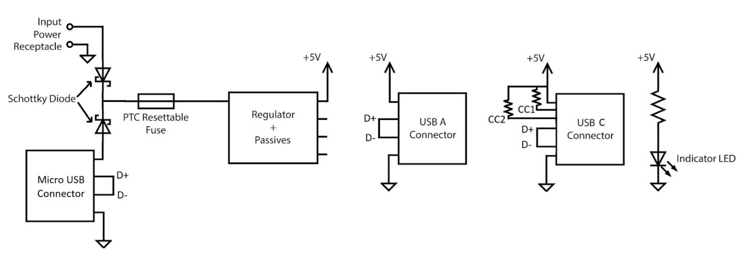
With the general specs in mind, it is time to “build” a circuit. Luckily, a high-level schematic diagram following the general specs has been already created for you, but the parts needed to implement it have yet to be chosen. Your job is to:
- Find out what is available: search DigiKey. For other projects, Mouser and online part search engines such as Octopart may be useful.
- Pick parts following the order below. As you do this, create a Bill of Materials (BOM). A BOM is a spreadsheet or table with the quantity, value, Manufacturer part number, distributor (e.g. Digikey) part number, cost, and other information about the parts you decide to use. For this BOM, please use this template!
The “Value” column in BOMs usually refer to passive values, such as the resistance of a resistor or the capacitance of a capacitor. Feel free to leave it blank for other kinds of components, or use it however you’d like. Additionally, the “Reference Designator” column refers to the annotated symbol reference, feel free to leave it blank until the schematic has been finished.
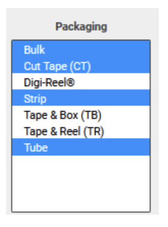
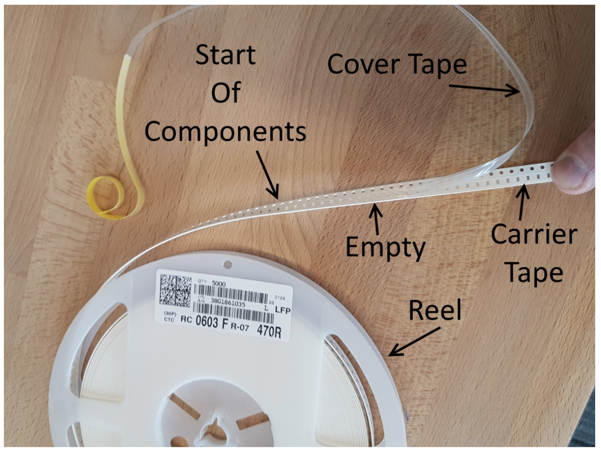
A note on packaging
We recommend selecting the Packaging filter while searching for components in this lab, which is not the form factor the component comes in (that is called Package/Case). Packaging is how the distributor organizes and ships your components; Tape and Reel, Digi-Reel, Tape and Box all have minimum quantities in the thousands and should be avoided (they are types of packaging that allow for components to be fed into machines for assembly). For hobbyists, Cut Tape for small parts and Bulk/Tube/Strip (typical for larger parts) are much better. You may see other packaging names; search the internet to find out more!
The World of USB
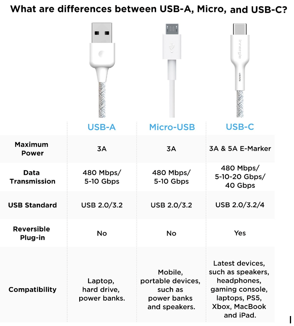
You have probably seen these ports on pretty much any electronic device you used recently. Let’s dive into what they are and what they do! Types of USB connectors:
For this lab, you will be using three different connectors out of the many options. These are USB-A, micro-B, and C.
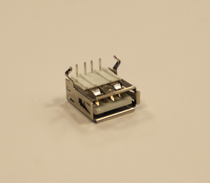
USB-A Receptacle A
USB Type-A female receptacles have 4 pins:
| Pin | Name | What’s it for? |
|---|---|---|
| 1 | VBUS | Put ~5V here |
| 2 | D- | Charger detection |
| 3 | D+ | Charger detection |
| 4 | GND | Put ground here |
Finding the USB-A Receptacle on Digikey
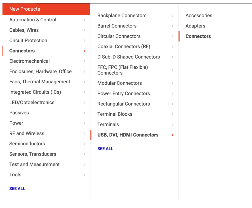
- What component are we looking for? A USB-A receptacle, which is a type of connector. This means we need to head to the “Connectors” section and look for the correct category. Click on the category and it should take you to a list of all of the parts in that category.
-
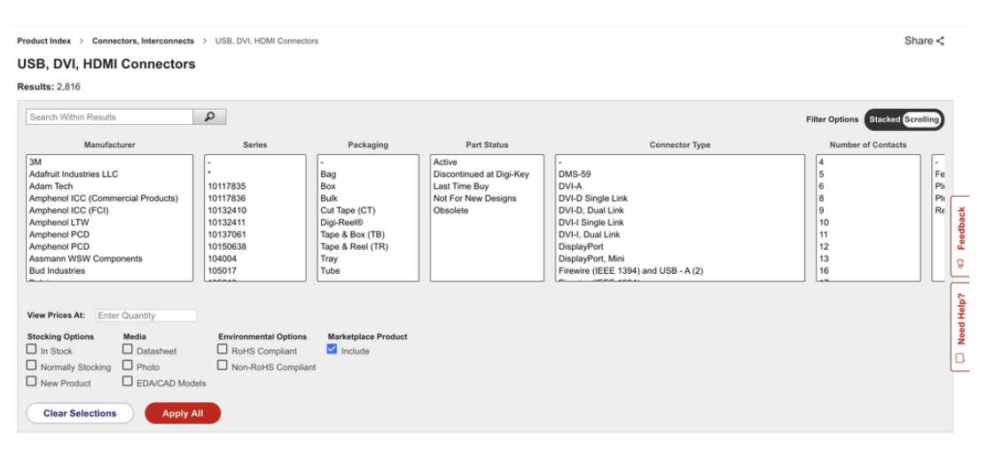
Now we are at the results page. There should be approximately 4,000 products to choose from and 19 categories to filter the selection by (that’s a lot).
-
As a preliminary step, check our standard filters: In-Stock, Datasheet, and Exclude Marketplace (“Marketplace” components are sold by third parties often with long lead times and high shipping costs). Part Status: Active is also good to include, ensuring you don’t use discontinued parts.
Due to the global parts shortage, we will be lenient about out-of-stock parts for this lab. Of course, for your project you must only choose in-stock parts. You should be able to find in-stock components, though.
- It turns out we mostly only care about two categories, connector type and gender.
- Select the correct connector type and gender filter (Hint: if you’re unsure look above again to see what type of part we are looking for).
- Now we should have narrowed down our search to around 275 results, but how do we select the final component? Try filtering by current rating * (see earlier in this lab) and the mounting type. We want a “right angle connector” which allows us to plug in parallel to the board (see image above), as opposed to a “vertical connector”, which sticks out normal to the board.
- Keep in mind that one of our specifications is minimum cost. So from here we can find the ‘Unit Price USD’ column and if you click the up-arrow underneath, it will sort all of the results by cost.
- You should now have your final USB-A receptacle chosen. Click on its DigiKey part number for more information on the component and fill out the appropriate columns in your BOM.
Feel free to set the current rating to 2A for now, you’ll calculate the current rating below.
Micro-B Receptacle
Following the same procedure as for the USB-A receptacle, choose a USB Micro-B receptacle from Digikey.
USB-C Receptacle
USB Type-C is the most recent development in the exciting world of USB, allowing for blazing fast data transfer (80GBit/s with Thunderbolt 5) and high-power charging (currently up to 180W!!). In Europe, nearly all new battery-powered electronics are required to have a USB-C charging port. As you can imagine, each of those have different voltage and current requirements, so they must have a way to talk to chargers and negotiate for their needs. Those methods of negotiation are detailed in the 440-page long USB Type-C Spec R2.4, among other things, but in summary, both the downstream device and upstream charger use USB PD (power delivery) controllers and communicate over the CC1 and CC2 lines in USB-C cables.
Take a look at these 3 different options for USB-C receptacles. In the past, project groups have used all of these with varying success. Take a look at the 3D models of each receptacle, how many pins are present, and where those pins are located.
Which one do you think will be the easiest to solder by hand? (Hint: there is a best choice here for the application in question: power delivery)
- Option 1: GSB1C4621DS1HR (inside of board, 16 pins)
- Option 2: USB4105-GF-A (on top of board, 16 pins)
- Option 3: 10152803-00011LF (on top of board, 24 pins)
Now, go to Digikey and add it to your BOM!
Diode Or-ing
Let’s say you’re working on a PCB for a robot safety system. If the board shuts off, the entire safety system will fail, endangering employees working nearby. To avoid this, you decide to power the PCB with two independent power supplies. If the voltages between the two supplies are too different, current will be pushed into one of them, potentially damaging it. To prevent this, we use diode ORing. Ideal diodes only allow current to flow in one direction (that’s why the symbol usually looks like a triangle pointing in that direction!). Putting diodes between each of the supplies only allows current to flow out of them. Besides providing protection between the two power sources, it also allows you to remove one of them without interrupting the power supply. This is great for maintenance, in the event that one of the two supplies fails. A Schottky diode is a type of diode commonly used in ORing because they have a low forward voltage, which is important for minimizing wasted energy (remember P=IV, and an ideal diode would have V=0). Besides diode ORing, they are also used to help protect a circuit from being connected in reverse, like if you accidentally connect the positive terminal of a battery to the negative terminal on your PCB.
Choosing your diodes!
When choosing a protection diode, it is important to look at the diode’s type, current rating, forward voltage, and DC reverse voltage.
-
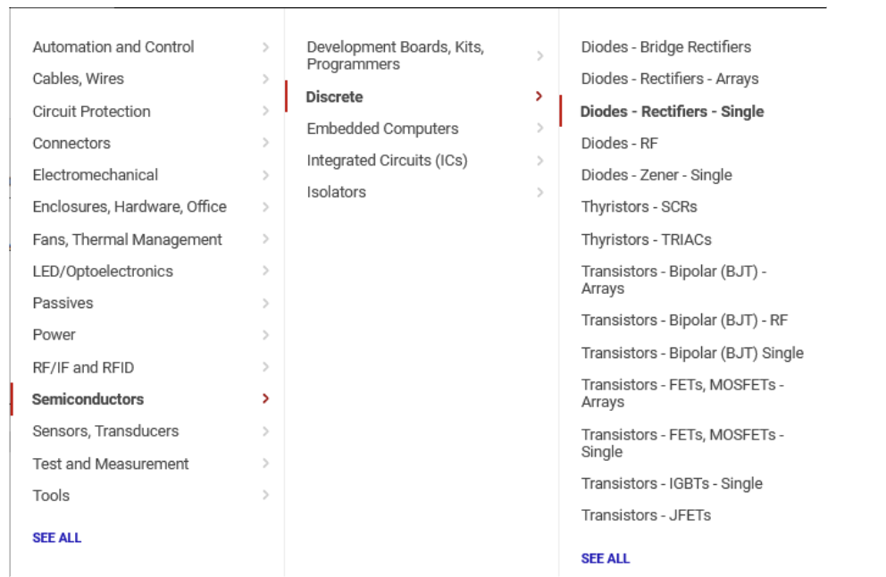
Navigate to diodes
- Now check our standard filters: In-stock, Datasheet, Part Status: Active, and Exclude Marketplace.
- Select the Schottky type (ignore the “reverse polarity” category, those are irrelevant specialty parts)
- Our requirement for forward voltage here is no more than 750mV at 3A. This means that at 3A going into the regulator, we’ll experience a 0.75V drop across the diode (at lower currents, this will be less). This drop is actually quite problematic, but we’ll ignore it for later parts of the lab (fuse sizing) for convenience.
- You should be able to find a reasonable diode now sorting by cost and making sure the package is hand-solderable. Choose an appropriate Schottky diode :)
- Add to BOM
Keep in mind that there are more solutions that we’ve listed here with respect to diode ORing; you may want to explore using a FET for higher-efficiency designs, for example.
Fuse
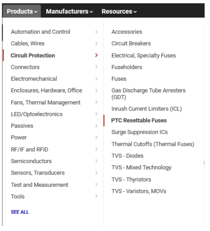
To protect the switching regulator from large transient voltage spikes or short circuits, we recommend using a polyfuse, aka PTC resettable fuse. This device heats up when high currents pass through it, increasing in resistance and thus effectively “opening” the circuit. After some time, the polyfuse will cool down and allow current to flow again.
To start, navigate to the PTC resettable fuse category:
As always, we’ll need to filter things down a bit. After selecting the Active, In-Stock, Datasheet, and Exclude Marketplace filters, we have about 2,000 parts.
Fuses have two major parameters:
- Hold current ($I_h$): the maximum sustained current for which the fuse is guaranteed not to trip. For us, this requires a bit of math.
-
Our regulator can output 1.5A out at 5V. Assuming the regulator has an 80% efficiency, use this power conservation equation to calculate the needed current on the input side: $V_{\text{in}} \cdot I_{\text{in}}\cdot \text{efficiency} = V_{\text{out}} \cdot I_{\text{out}}$
Hint: in the worst (max input current) case, the input voltage is our minimum, 3.6V.
-
- Trip current ($I_t$): Let’s set a maximum trip current of 5A; anything higher risks serious damage to our circuitry. You should see about 30 parts that fit these criteria. Choose based on package and cost.
Light-Emitting Diodes (LEDs)
LEDs are typically not covered in great detail in lower-division classes. As the name implies, LEDs are a type of diode, a semiconductor device. Like other diodes, LEDs have a highly nonlinear relationship between voltage and current! Unlike resistors, they do not obey Ohm’s law (V=IR, where V/I $\neq$ constant R). Instead, you can think of them as having a highly variable resistance (V/I slope).
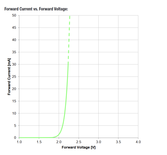
In the plot below, we can see that applying 1.5V to the LED will cause almost no current to flow; however, applying more than 2.3 or 2.4V will instantly burn out the LED (infinite current causes things to heat up rapidly).
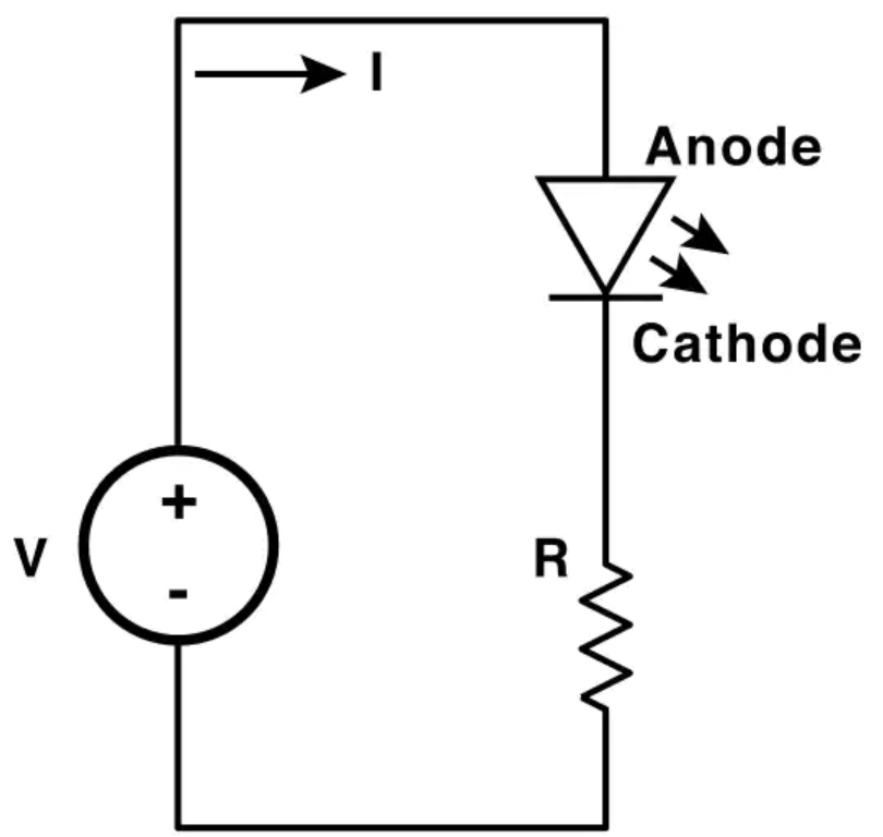
Since we can’t (cheaply) provide precisely 2.2V, we generally use a resistor in series with the LED to “drop” the remainder of the voltage from a typical (5V or 3.3V) supply in a stable manner. Without this, even slight variations in voltage would easily destroy the LED, as the current would spike!!
In order to use an LED, we will follow this procedure:
- Pick a desired current. This corresponds to the brightness; while every LED is a little different, for an indicator around 10-15 mA should be visible (more can be painful to look at).
- Find the forward voltage at the current. In DigiKey, manufacturers typically use “test currents” of around 10-20 mA to calculate the “nominal forward voltage” listed in the search filters. In reality, the forward voltage will differ based on how much current is running through the LED (see above)!
- Figure out what size resistor we need in series with the LED to ensure exactly the desired current will run through the LED with the given supply.
As an example using the graph above and a supply of 5V:
- We pick 10mA.
- The forward voltage appears to be around 2.2V at 10mA.
- If we have a 5V supply and a drop of 2.2V across the LED, there will be 2.8V across the resistor in series with the LED. Using V=IR, we need a resistance of R=2.8V/0.010A = 280 Ohms!
We will start with the LED Indication - Discrete category; there are several categories of LEDs, but this one works well for indicators and has many parts.
Choose the standard general filters (In-Stock, etc.).
Pick using your newfound knowledge about forward voltage and test current, and confirm your choice by checking the datasheet. We also require that your chosen LED have a SMD footprint, not through-hole. Be sure to also choose an appropriate resistor near the value you calculated earlier with an SMD footprint too (we recommend choosing either 0805 or 0603 (imperial) SMD sizes for both the LED and resistor, but you’ll notice LEDs often come in larger sizes too).
Switching Regulator
The switching regulator has been decided as the voltage conversion method. Your job is to find an appropriate switching regulator for this application.
- Output voltage: 5V. Must be able to be set up to output 5V. This means adjustable output types are ok so long as the necessary feedback network for a 5V output is implemented.
- Output Current: 1.5A. Must be able to output 1.5A, which is the desired USB charging current. Technically, the spec allows for significant voltage “droop” at 1.5A, or even chargers that drop below 2V before sourcing 1.5A. However, the behavior of switching regulators exceeding their max current limits is not always consistent.
- Input Voltage: 3.6V to 4.8V. Switching Regulators will have a defined input range. Most likely the only limit you will need to worry about is the lower limit of 3.6V as the upper limit will probably be much higher.
- Switching Frequency: above 100kHz. The non-DC frequency content of the regulator output is beyond the scope of this course, but there’s plenty to explore here if you’re interested.
We have two options that we have chosen for you that will meet all the above requirements and have the ability to output more current than we have set as the requirement above:
- LTC3872
- TPS61023
You are also free to look for other regulators that meet the above requirements. Search up these parts and take a quick look at their info pages on Digikey. We will hint that one of these will be easier to use for this lab than the other, so we recommend looking at both parts’ datasheets.
Passives
Like we talked about in lecture, many ICs will have accompanying passives associated with that component. This will generally be in the “Application Circuit” section of the IC datasheet. Some datasheets may even include recommended passives (including part numbers) to use. To answer the below questions, skim and look through the entire datasheet for the regulator you chose.
For the LTC3872 part we listed above, the example circuit on the first page is a good reference for what we want to build. For the TPS61023, the 12th page is what you want to look at.
Depending on your answers to the above (mainly the regulator you chose and the USB connection between D+ and D-), you’ll need some passive components like resistors, capacitors, and inductors. For each component:
- What value(s) do you need?
- In what form factor?
- With what kind of component tolerances?
- With what kind of component parasitics? A parasitic is a property of a component that is non-ideal, e.g. the resistance of a non-ideal inductor or the capacitance of a non-ideal resistor. For this lab, this is really only important for the inductor (DC Resistance, DCR) and output capacitor (Equivalent Series Resistance, ESR) for the regulator. The datasheets will explain about these.
Once these questions have been answered for each passive needed, add them to your BOM. As always, when searching on Digikey, remember to apply the standard filters: In-Stock, Datasheet, Part Status: Active, and Exclude Marketplace.
We also will need a few passives for our USB-C upstream port. Since we are only delivering 5 volts at 1.5 amps through our USB-C port, instead of a USB PD controller, we can place 22kΩ pull-up resistors on CC1 and CC2 to indicate that power delivery combination to our downstream device. Find and add two 22kΩ resistors to your Digikey cart and BOM. Because they are only used as pullups, you don’t need to be very careful with your selection.
Some tips for finding passives
Resistors and Capacitors
A lot of the time if you are looking for general resistors and capacitors (nothing that needs high power dissipation or ultra high-precision/stability), once you find one value of a component it’s easy to keep finding other values from the same family. Here’s an example for a resistor:
Let’s say you are looking for a 1kΩ resistor in an 0603 package and find this part, the RC0603JR-131KL. Notice in Digikey that this part is from the RC_L family and that if you click on that you are directed to all the parts in the family. This can make sorting down parts in Digikey much faster. Also note that the footprint and value are in the part name (0603 and 131K, respectively, though the value may be confusing for this particular part); if you just change the right sections of the part name many times you’ll just get the part you are looking for immediately (and Digikey search will often suggest the right part number even if you type it wrong).
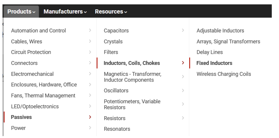
Inductors
Inductors are a lot less commonly used than resistors and capacitors, but you’ll almost always find one in a switching power circuit, such as our application here. You’ll want to search in Fixed Inductors:
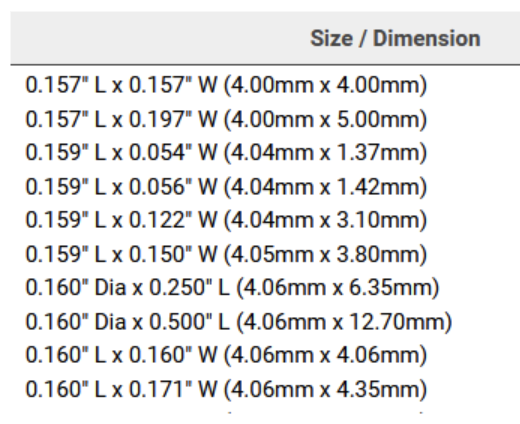
The three important search factors for inductors being used for this power application are the inductor value (L, in Henries), saturation current, and DC Resistance. Follow the recommendations in the datasheet for the part you’ve chosen for each of these factors (they cover the math, but for a more thorough understanding of calculating inductor requirements, take EE 113 Power Electronics!). For example, the TPS61023 recommends using an inductor with 1 uH value, 9.0 A saturation current, and a DCR of sub 15 mOhm (ideally, DCR is 0, so the general idea you want is to minimize the DCR in the inductor you find). As for footprint, inductors are really just packages of coiled wire, so unlike resistors and capacitors, it is more common to find inductors in weird, non-standardized packages described by their dimensions. For this lab, try to source an inductor around 4mm x 4mm (there are a lot of very close dimensions, try searching with all of them).
Lab Checkoff
Read Section 4.4 “Dedicated Charging Port” in the USB Battery Charging Specification, Revision 1.2. Make sure to pay attention to the third paragraph in part 4.4.1 “Required Operating Ranges.”
Answer the following questions:
- What is the allowable range of output (VBUS) voltages from your charger?
- What is the maximum value of I_DEVCHG? Hint: Look at Table 5-2
- If a device is drawing 0.25A, what is the minimum voltage the charger can output? Hint: Look at Figure 4-2
Your charger should connect the D+ and D- pins to indicate that it is a charging port. These pins can be connected in a variety of ways, but we’ll simply short them together. See Figure 2 in this application note for details on ways to configure this.
Read section 4.11 “Parameter Values” in the Type-C spec, and answer the following question:
- If we had connected pullup resistors with values of 10 kΩ instead of 22 kΩ on the CC lines, how would this affect the PD current the USB-C port advertises?
Make sure you have…
- Answers to which USB-C you chose and why
- Answers to the USB Charging Spec questions
- A BOM with:
- USB-A receptacle
- USB micro-B receptacle
- USB-C receptacle
- Fuse for overcurrent protection
- Schottky diodes for diode ORing
- SMD indicator LED and resistor
- Switching regulator (DC-DC power conversion)
- Additional components/passives related to the switching regulator (capacitors, resistors, inductors, possibly a transistor) and the USB-C connector
- You do not need to worry about input power from the batteries (we will use a standard pin header)